Topics
Thermostat
Not satisfied with the current offerings of network-connected thermostats, I went ahead and made my own.
Getting Started
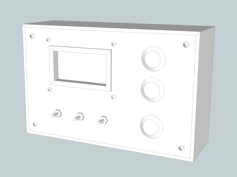
I had a vague idea of the aesthetic I wanted: a wooden case with stainless hardware, flush mounted to the wall. So I got to drawing some designs and ultimately landed on this.
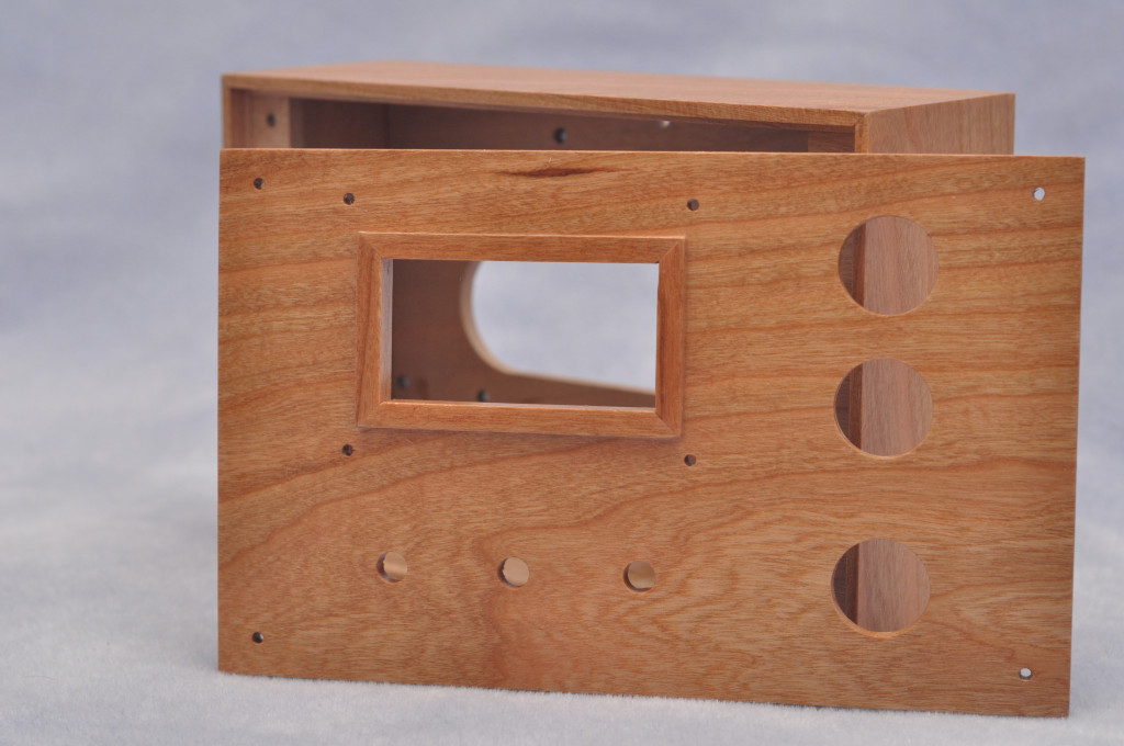
I picked up a 1/4" thick cherry plank from the local lumber store to use to make the enclosure. After assembling the box, I installed #2-56 t-nuts on the back. These retain the bolts that the internal components attach with. This was some of the tiniest hardware I've ever used!
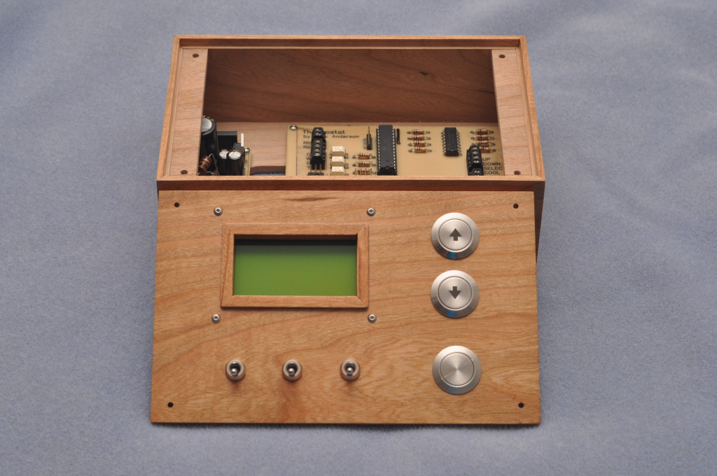
The front panel attaches in a similar way, and has holes drilled in it for all of the panel-mount hardware. Here it is after the final coat of polyurethane.
Assembling the Components
I chose a Honeywell HumidIcon temperature/humidity sensor, since it provided the accuracy I wanted for a reasonable price. The LCD assembly was from SparkFun, and the network interface was a premade W5100 breakout board.
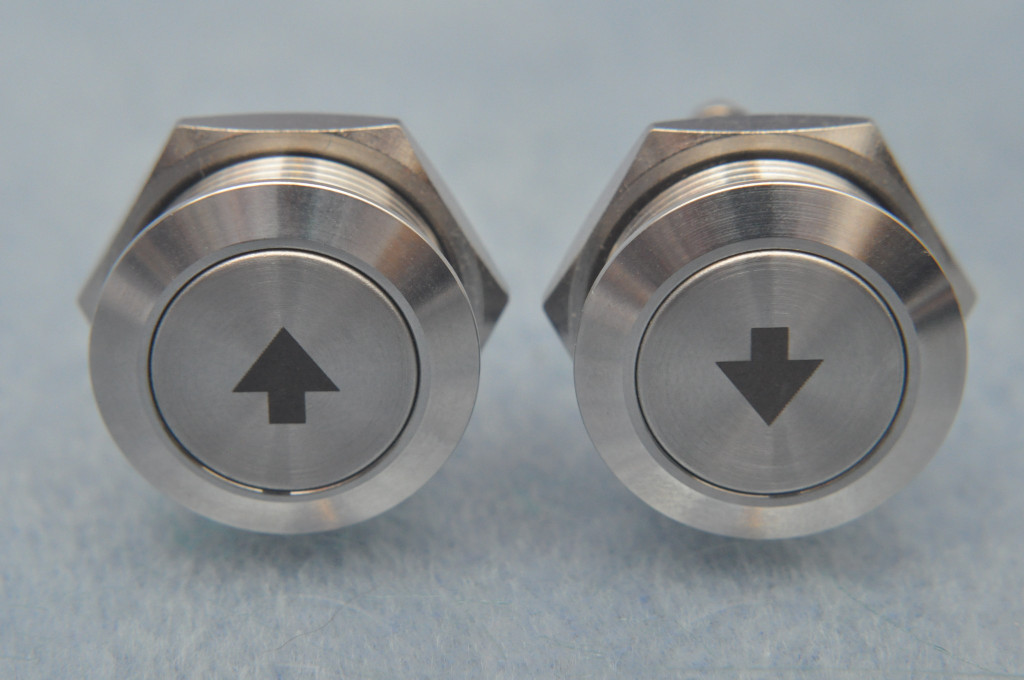
I really liked these stainless steel buttons I found on DigiKey.
The action on the buttons feels quite nice. They're not "clicky" but they are very responsive to presses.
Building the Circuit Board
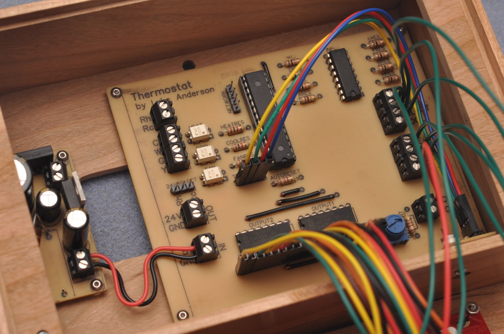
After putting the components together on a prototype board, I designed three printed circuit boards with DipTrace: one for the main components, one for the temperature sensor, and one for a 24VAC-to-5VDC switching power supply.
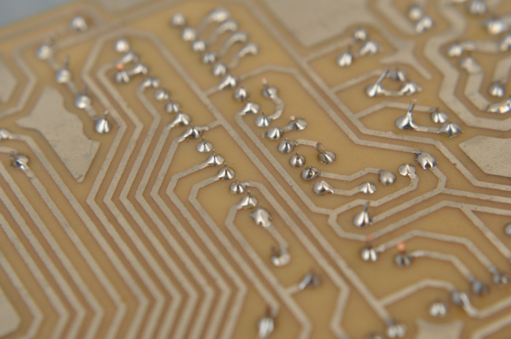
I already had copper-clad laminate purchased from RadioShack a long time ago, as well as the etching and tinning solutions. I used the toner transfer method. Basically, the process goes like this:
- Print the mask onto glossy magazine paper with a laser printer. Those shiny department store advertisements that come in the weekly junk mail are perfect for this.
- Use an iron to heat up the PCB.
- While it's still hot, place the mask face down onto the copper layer.
- Heat it further with the iron, and the toner will adhere to the copper.
- Wash off the paper, and then soak the PCB in ferric chloride until the exposed copper has dissolved.
- Clean the whole thing with acetone and you've got a nice shiny circuit board.
- Dip in a tinning solution to prevent it from oxidizing, which makes it easier to solder the components later.
- Drill a LOT of holes with the drill press.
- Print the silk screen layer onto transfer paper, and apply that with the same ironing process.
Voila. Homemade PCBs, ready for the components to be soldered to.
This process isn't super precise, so I made the traces fairly large and spaced apart to compensate for any imperfections in the toner transfer. But it turned out pretty good, all things considered.
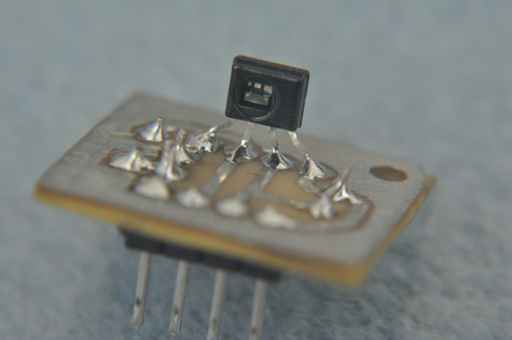
Here's a closeup of the temperature sensor. It's quite small. I put it on a separate circuit board to keep it far away from the other components (which could generate heat). This also made it easy to insert into a hole drilled in the bottom of the enclosure, allowing it to have direct contact with the room air.
With all that complete, it was time to put it all together!
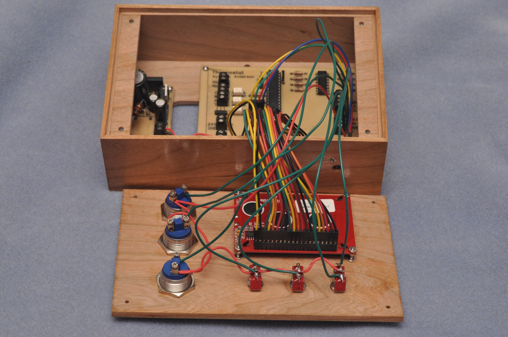
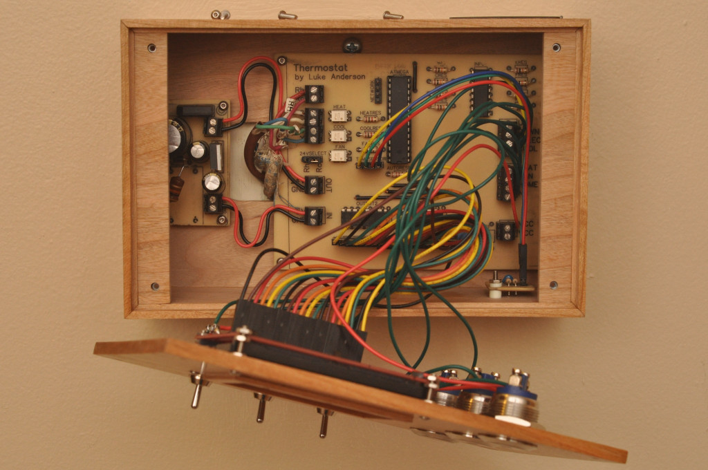
There are quite a few wires to connect, primarily for the LCD. (Note: the network interface is not pictured here. I added it later.)
It mounts to the wall with two screws in the back of the enclosure.
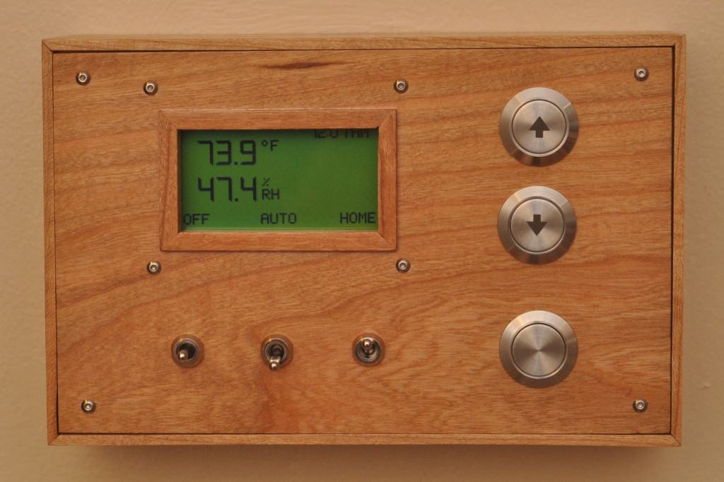
And there it is! Fully assembled and working.
Writing the Software
The software was a fun exercise in optimization. The microcontroller has a very small amount of memory (32KB of flash memory for the code, and 2KB of RAM), making it a challenge to fit all of the features I wanted. The stock Arduino libraries were simply too bloated to achieve this, so I wound up writing my own wrappers for the core AVR functionality as well as the W5100 ethernet interface.
Every byte counted here. For example, the fonts I made for the LCD took up quite a lot of space initially, but I managed to condense them down quite a lot:
- 87 bytes for the large font (digits only)
- 355 bytes for the small font (digits, uppercase, lowercase, and a few symbols)
Pixel-based fonts are fun!
I knew I wanted network support, to be able to monitor and control the thermostat from the LAN. (Remote access would be easily achieved by a VPN into my home network.) This meant writing a few services:
- DHCP client (to acquire an IP address automatically)
- NTP client (to keep the clock accurate)
- HTTP server (to retrieve status and change settings)
The HTTP server supports basic access authentication using a randomly-generated username/password that can only be viewed on the thermostat's screen, from the settings menu. It will respond to GET requests with a JSON object containing the current state, and POST requests can be used to modify settings.
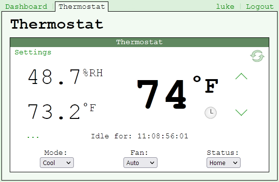
All of this gets wrapped up with a nice web interface for easy access.
Final Thoughts
I completed this project back in 2015, so this has actually been in use for over 7 years now and it's worked quite well.
I wound up removing the 24VAC converter and just wiring a 5V USB power supply directly into it. This was for a few reasons:
- It was generating a bit of heat inside the enclosure.
- The 24VAC was supplied by the air conditioning system, because the boiler does not have an externally accessible 24V transformer. But unlike the boiler, the AC is not on a generator-powered circuit, which meant no heat during a power outage. Moving it to an outlet on the same circuit as the boiler solved that.
- The air conditioning system has since been replaced with a Mitsubishi heat pump. More on that in a future post!
Overall I'm very pleased with how this project turned out. I'm beginning to ponder what version 2 will look like.
